Tunnelling: The Kombilösung project in Karlsruhe digs forward
- Like
- Digg
- Del
- Tumblr
- VKontakte
- Buffer
- Love This
- Odnoklassniki
- Meneame
- Blogger
- Amazon
- Yahoo Mail
- Gmail
- AOL
- Newsvine
- HackerNews
- Evernote
- MySpace
- Mail.ru
- Viadeo
- Line
- Comments
- Yummly
- SMS
- Viber
- Telegram
- Subscribe
- Skype
- Facebook Messenger
- Kakao
- LiveJournal
- Yammer
- Edgar
- Fintel
- Mix
- Instapaper
- Copy Link
Posted: 12 March 2015 | Alexander Pischon & Uwe Konrath, Joint General Directors, KASIG
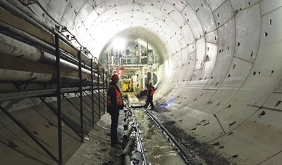
Work has recently started on the 2km-long tunnel ducts under Karlsruhe’s Kaiserstraße which will accommodate the light-rail tunnel section as part of the overall Kombilösung project. The cutting head of tunnelling machine ‘Giulia’ is now continuously driving below Karlsruhe in a westward direction. For Intelligent Transport, Alexander Pischon and Uwe Konrath – joint General Directors of KASIG, the company behind building the new infrastructure – delve into the project’s tunnel construction details…
The Kombilösung comprises two elements: a light-rail tunnel with a branch tunnel for south-bound lines, which will make room for an aboveground rail-free pedestrian zone, plus an attractively landscaped area around a tram line built on top of a road tunnel underneath Kriegsstraße.
The 80m, 1,300 tonne Herrenknecht AG tunnelling machine, named Giulia, has already worked carefully through the so-called ‘sealing plug’ and subsequently through the subterraneous ‘curtain’ of the future underground train station at ‘Durlacher Tor’. The sealing plug – a concrete wall approximately 1m-thick (in front of the train station wall) – initially accommodated the 9.32m-diameter cutter head. With a thickness of approximately 1.20m, the subterraneous curtain directly follows this and is made of reinforced concrete, and located exactly where the cutter head is tunnelling through. Instead of featuring steel reinforcements, it features a fibreglass-strengthened plastic (GfK) reinforcement which breaks under the impact of the cutting head’s tools. Behind the subterraneous curtain, a sealing block (approximately 15m-thick) awaits. When tunnelling, the substrate (which was previously strengthened with shotcrete) ‘relieves’ the intersection between the subterraneous curtain and the gravel/sand substrate: to the rear, it seals the underground station from any groundwater that is present externally and bridges the area until the installation of the first tubing ring.
Giulia will only achieve its intended average performance of 8-10m of tunnelling a day once the ‘start phase’ has been achieved. The tunnelling machine is expected to reach its destination (behind the Kaiser memorial on the Kaiserplatz near Mühlburger Tor) in August/September 2015.
‘Giulia’ facts and figures
With its cutting head, guard, bridge and trailers, the ‘S 869’ has an overall length of 80m and weighs 1,300 tonnes. With a diameter of 9.32m, the cutting head is specially adjusted to the tunnel under the Kaiserstraße. Two light-rail lines will run face-to-face through its shafts. Twenty-seven cutting rollers – so-called ‘double-discs’, 16 clearers and 172 skimmer blades will ensure that, metre-by-metre, gravel and sand is carried away. With overall power of 1,210 kW from 11 electric motors, Giulia will slowly advance under the pedestrian area using 18 propulsion cylinders whilst the city’s urban railway and trams are still running. The route will go just short of 2,050m in a westward direction, under supply lines and drains and centrally through the planned stops (which until such a time, have been constructed as shell structures) and the triangular junction on the market square (Marktplatz) featuring a total of eight excavation walls. Gravel and sand will be ‘liquefied’ using Bentonite and pumped via a pipe to a processing site at Durlacher Tor which will recover the liquid and supply it back west of the tunnelling machine. Giulia will move along its route with its crown at least 4.50m (maximum 9.50m) below the pavements of Karlsruhe – and in doing so, will always remain below the groundwater level, which is at a depth of approximately 3m.
The actual tunnel is created under the cover of the shield tail of the tunnelling machine, directly behind the cutting head and the hydro shield: the ‘erector’ of the tunnelling machine constructs a concrete ring with an inner diameter of 8.20m from six tubings, each 40cm-thick and each weighing nine tonnes. Each individually-manufactured concrete ring serves to propel Giulia because they prop up, in order to generate the pressure to remove the ground that is present at the front, at the cutting head.
Separation plant
The separation plant is set up on the eastern construction site (Baufeld Ost) at Durlacher Tor. It fulfils a key role because soil that is excavated from the cutting head at the tip of the tunnelling machine is transported here via thick pipes and subsequently processed. A pulp-like mixture comes from the pipeline which is made up of Bentonite and then added in the tunnelling movement and the excavated soil which, in Karlsruhe, is essentially made up of sand and gravel. The separation plant separates the Bentonite from the soil and following additional treatment, supplies the Bentonite back to the tunnelling machine in a circuit.
The separating plant partially works like a spin dryer: the incoming sand-gravel-Bentonite mix is initially supplied via different size sieves; in doing so, coarse material is removed from the pulp. In further work steps, the remaining mix is channelled into centrifuges (cyclones). This is done in order to separate the fluid from the solid matter. This fluid is mainly the Bentonite which has a stabilising effect of when the soil is excavated by the cutting head at the tip of the tunnelling machine. The released Bentonite is analysed before being fed back to the tunnelling machine; if the proportion of solids in the suspension is correct, the fluid can be pumped back into the circuit. In all other cases, residue is collected in a basin with used Bentonite. In order to keep the circuit stable, new Bentonite is added in proportionately to the used material which is removed.
The separation plant is encapsulated against noise. This is because it – just like the tunnelling machine – works day and night. Approximately 127,000m3 of sand and gravel will be excavated when building the 2km-long shaft under the Kaiserstraße. Bentonite will be separated from this by the separation plant. Sand and gravel which has had Bentonite removed from it will be used for a new purpose, e.g. the filling of spaces.
Excavation methods
In contrast, a totally different technique will be used for the 250m-long section of tunnel on the southern branch of the T-shaped future light-rail tunnel under Karl-Friedrich-Straße between the Marktplatz and Ettlinger Tor; shotcreting or the New Austrian Tunnelling Method (NATM).
The tunnel is constructed using underground excavators and the subsequent introduction of an injected concrete vault with steel mats and steel arches. In addition, this technique significantly spares the residents disruption compared to open (cut and cover) tunnelling. NATM was developed in the 1950s and uses the natural carrying capacity of the existing soil. In order to give the sand-gravel mix under Karl-Friedrich-Straße greater carrying capacity, the soil was improved before the actual construction of the tunnel using shotcreting from above. Later, excavation can take place underground. The securing of a tubular hollow cavity (resembling a flattened oval) in the improved soil takes place using shotcreting in connection with anchors, reinforcing mats and tunnel arches. This way, a cavity free composite construction is created between the structure and the soil.
The soil improvement takes place under a further aspect; as the underground excavation of the tunnel takes place below the groundwater table, in the tunnel cavity that is created increased air pressure must act against the pressure of the groundwater and displace it. In this respect, people and machinery, as well as the spoil are brought into the tunnel/out of the tunnel through locks. The soil improvement (through the shotcreted concrete) also serves to prevent the excess pressure under the earth from escaping upwards.
Alternatively, smaller tunnel sections are created using the open (cut and cover) method by opening up a trench (subterraneous curtains, high pressure injected base) and excavation following engineering results in a rectangular tunnel. Examples include: between the station at Durlacher Tor and the ramp in Durlacher Allee; between the end of the tunnels made with the tunnelling machine and the ramp at Mühlburger Tor; in Ettlinger Straße between the stops at Ettlinger Tor and Kongresszentrum; at the southern end of the southern branch at the level of the Vierordtbad; and at the T-junction at the market square (Marktplatz).
The tendering process for the body shell of the Kriegsstraße tunnel
In early-December 2014, the tendering process for the body shell of the Kriegsstraße street tunnel (in addition to the construction of the light-rail tunnel, the second subproject in the Kombilösung) was forwarded to six consortia in total. Following the prequalification stage, the six consortia were admitted to the tendering process and now have until 26 March 2015 to submit their proposals. It is estimated that the work to build the body shell will then start before the end of September 2015.
The tunnel in the Kriegsstraße and at the western end of Ludwig-Erhard-Allee is approximately 1.4km-long and has two shafts. The tender process covers 6,130 items, a description of the construction and details of the work/performance. It has 2,250 pages, 395 plans, 230 design plans and 165 completed drawings and has to be read by the engineers.
The automobile tunnel in the Kriegsstraße and Ludwig-Erhard-Allee will be built using the open (cut and cover) method: first of all, subterraneous curtains or drilled piles are inserted into the soil followed by the base. The excavation of soil then takes place in the U-shaped ‘box’.
This is then followed by the insertion of the base plate, the walls and last but not least, putting on ‘the lid’ (the ceiling). The excavation spoil amounts to 300,000m3. Approximately 98,000m3 of concrete and 22,800 tonnes of steel are used. In total, 47,000m2 of subterraneous curtains has to be produced, as well as 18,500m2 of piled walling. Approximately 90km of anchoring ensures stability in the trenches. The tunnel creates 24,000m2 of road space for the cars.
Tunnel tube facts and figures
- Tubing outer diameter: 9m
- Tubing inner diameter: 8.20m
- Tubing length: 2m
- Tubing weight: 9 tonnes – 54 tonnes for a ring made from six tubings
In all, approximately 6,000 tubes are needed for the route of the tunnel which is the equivalent to 21,600m3.
Biography
Alexander Pischon graduated in Economics from the University of Heidelberg and later restudied for a PhD from the same university. His early career saw him take roles within ABB Management Consulting GmbH and ABB Leistungszentrum Elektronik GmbH, then taking roles of Head of Business Development within DB Energie GmbH and DB Stadtverkehr GmbH. From 2008 until summer-2014, Alexander was Chairman of Regional Management of DB Regio AG, and is currently Managing Director of Verkehrsbetriebe Karlsruhe GmbH (VBK) and joint General Director of Karlsruher Schieneninfrastruktur-Gesellschaft mbH (KASIG).
Uwe Konrath graduated in Structural Engineering from the University of Applied Sciences of Rhineland-Palatine at the Trier Department and started his career as a Surveyor for an engineering office. He later became Assistant in the Faculty of Civil and Structural Engineering at the same university that he studied. Uwe later worked as a Planning Engineer for Deutsche Bundesbahn and Project Supervisor for Verkehrsbetriebe Karlsruhe GmbH (VBK). Since 2012, Uwe has been joint General Director of Karlsruher Schieneninfrastruktur-Gesellschaft mbH (KASIG).
Related topics
Business Models, Infrastructure & Urban Planning
Issue
Issue 1 2015
Related modes
Light Rail
Related cities
Germany
Related organisations
KASIG